Accueil > Parc mobile > Contrôle des antennes > Procedure for verification of antennas in Meudon
Rechercher
Procedure for verification of antennas in Meudon
par -
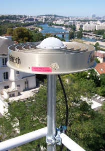
We describe the method used to verify the antennas included in the mobile pool of GNSS receivers. Verification takes place on the terrace of building 2 in Meudon Bellevue campus.

The test bench was progressively installed over the first half of 2008 by Charles Deléglise, from the mechanics workshop of the Technical Division, and David Stuart, before he went to his definitive position in La Seyne sur Mer. Coaxial cables measuring more than 30 m were custom-made to link the antennas to receivers located in the GNSS workshop on the first floor of the building. A specialized company was contracted to drill through the wall of the building to make the cables accessible inside the workshop.
10 stainless steel tubes were placed on the terrace railing, spaced around 90 cm apart. Specific parts were machined to allow the antennas to be installed on the summits of these tubes.
The arrival of Benoît Arnold on 1st June 2009 made it possible to initiate the verification operations starting the following September.
 An Ashtech ChokeRing antenna was chosen to serve as reference antenna. This antenna always occupies the IN01 position in calculations.
The verification procedure selected was that of the 2007 measurement campaign on the terrace of the IGN at Saint Mandé : each antenna records for around one week ; half-way through the week the antenna is rotated 180° in the horizontal plane. The jump in the time series at the moment of rotation equates to twice the positioning error. Obviously, this procedure does not provide information on performance in the vertical component. However, based on the few antennas that have been revealed as defective in the past, the defect was never in fact specific to a component or frequency. In addition, jumps in position in the range of one centimetre between days are often observed with defective antennas (we hypothesize that, as the model is not appropriate, the calculation solution is not “stable†).
For it to be rigorous, this procedure requires the creation of a model antenna specifically oriented “South†. A new antenna code must be created to be included in the gamit files rcvant.dat, antmod.dat and hi.dat. We chose to replace the first letter of the code of origin with a Z. Thus, the traditional ChokeRing 700936E antenna, for which the gamit code is ATDMCE becomes ZTDMCE. Since the 2007 verification campaign, the models for phase centre variations have become much more complex, and the use of a robot for absolute calibration produces elevation and azimut tables that can no longer be treated by hand.
A short Perl programme had to be written. This programme takes as input the IGS designation of an antenna and searches for it in the antmod.dat file. The programme returns the table corresponding to a South orientation of this antenna to the standard output. In practice, we redirect this output to a zntmod.dat file where the South oriented models of the antennas being tested are stored, we then concatenate the antmod.dat file of gamit tables (gg/tables/) with zntmod.dat to produce the antmod.dat file in the experiment folder (calb/tables/).
Only full measurement days are processed (but all data are archived). Thus, in a 7-day week one direction is always processed for a day more than the other. If a problem appears in the 5-point time series, the antenna is retested. As the aim is to determine rapidly whether the antenna can be sent out on a subsequent mission, calculations are performed with rapid orbits (available within 48 hours) and generally not recalculated when the final orbits become available.
In the comments field of the station.info file, an abbreviated 5-character name is given to the test antenna (e.g. CR910 for the 15910 ChokeRing antenna ; G7139 for the 7139 Geodetic 4 Ashtech antenna). This field will be used during extraction of the results to add the name of the relevant antenna as a comment to each time series.
Once the calculations have been performed in L1_ONLY and L2_ONLY (daily directories are “post-fixed†with “a†and “b†, respectively), a script extracts the baseline values for IN01 in the “set ambiguities†solution from the 0 files for a given year and creates files of values for each component and frequency (e.g. IN04b.2009.val contains the values for position 4 in L2 for the year 2009). The script also creates a comments file for each position from the station.info file (e.g. IN04.2009.comment for position 4 in 2009). This comments file contains the name of the antennas and their respective installation dates in the appropriate format for the pstext command from GMT.
A final script uses these files of values to calculate the mean value and trace the time series for each component and frequency. The comment files are used to add the names of the tested antennas to each graph. The X-axis is in Julian days and we have not sought to develop a method to remove the blank zones between non-contiguous measurement weeks.
The RINEX files for these measurements are available here..
Dans la même rubrique :


